Follow Us


Digital VHDL Simulation
VHDL (VHSIC (Very High Speed Integrated Circuits) Hardware Description Language) is an IEEE- standard hardware description language used by electronic designers to describe and simulate their chips and systems prior to fabrication. TINA versions 7 and higher now include a powerful digital VHDL simulation engine. Any digital circuit in TINA can be automatically converted a VHDL code and analyzed as a VHDL design. In addition, you can analyze the wide range of hardware available in VHDL and define your own digital components and hardware in VHDL. The great advantage of VHDL is not only that it is a IEEE standard, but also that can be realized automatically in programmable logic devices such as FPGAs and CPLDs. TINA can generate a synthesizable VHDL code along with the corresponding UCF file if the Generate synthesizable code checkbox is set in the Analysis/Options menu. You can save the created VHD and UCF files with the “Create VHD & UCF File” command in the T&M menu. You can read these files with Xilinx’s free utility Webpack, generate the bit-stream file describing the implementation of the design and then upload it to Xilinx FPGA chips. Example: The following circuit is a counter, defined in VHDL.

Run the simulation now with TINACloud, embedded in the window above
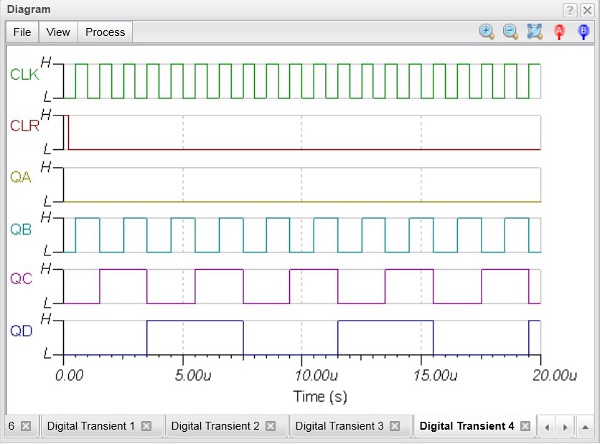
or invoke TINACloud in a new Tab of your browser by clicking here Running Analysis / Digital VHDL simulation, gives the following diagram:
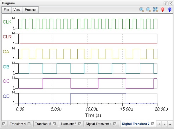
In TINA you can change the VHDL code and see the effect immediately. Change the line Pre_Q <= Pre_Q + 1; above to Pre_Q <= Pre_Q + 2; and close the dialog. Now Analysis / Digital VHDL simulation yields the following diagram–library ieee; use ieee.std_logic_1164.all;
use ieee.std_logic_arith.all;----------------------------------------------------
ENTITY counter is port( clock: in std_logic; clear: in std_logic; QA, QB, QC, QD: out std_logic); END counter;
----------------------------------------------------
ARCHITECTURE behv of counter is
signal Pre_Q: unsigned( 3 downto 0 );BEGIN
-- behavioral description of the counter
process(clock, clear) begin
if clear = '1' then Pre_Q <= "0000"; elsif (clock='1' and clock'event) then
QA <= Pre_Q(0); QB <= Pre_Q(1); QC <= Pre_Q(2); QD <= Pre_Q(3);
Pre_Q <= Pre_Q + 1; end if; end process;END behv;